Subaru
SVX
Receiver and Speaker Installation
Version
3.08
By
David Carter
[Table
of Contents] [Section 1:
Introduction] [Section 2: Radio Removal / Replacement] [Section
3: Speaker Removal / Replacement] [Section
4:
Final Notes] [Next] [Previous]
Several things have made this task a little difficult:
-
Looking at the dash, it's not
immediately obvious how to find the screws that secure the metal radio
"cage" (the part that holds the radio). Once you know how, the
removal procedure is very straightforward. There is also some
misinformation out there. For example, the instructions by
accessory manufacturer Scosche (which Crutchfield sent to me) tell you
to disassemble nearly half of your dash, including removing the Climate
Control module, to reach the radio. You do not need to do
that!
-
On the assembly line, Subaru
installed the factory radio before the interior trim (the nice, padded
parts of the dashboard). There is very little clearance when you
try to slide the radio cage out through the front dash opening.
Most of the edges of the metal cage are very sharp, so you'll need to
take extra care to prevent it from scratching up your dash and
gearshift lever.
-
There is a trick to the antenna
cables: The ones coming out of the factory radio are about 17"
long! They really are terminated with traditional
Motorola connectors, but those plugs/jacks are hidden under the carpet
on the left side of the transmission hump. You should not
cut these wires!
-
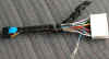
Several companies make
after-market receiver wiring adapters. At various times some of
these manufacturers have claimed that they carried the correct
adapter for the SVX. Believe me: They do not. If
their catalog lists an adapter for the SVX, it is the wrong
connector. Outside of Europe, all SVX model years (1992-1997) use
the same, unique
20-position connector. The connector in the SVX is different
than
those in all other models of Subarus. Unfortunately, the SVX
never had sufficient sales for it to be worthwhile to these companies
to
manufacture and sell the correct adapter. However, after much
research and legwork, I put together a proper solution. See this link
for more information. SVXs in Europe use the same harness
found on older Subarus (two connectors with 7 and 9 pins), which I now
have available. E-mail me for details.
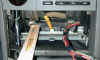
- The radio cage is a tight fit inside the dash
(depth-wise). When you slide the cage back into place, there
isn't much room behind and around the cage for excess wire. It's
very easy for the antenna and speaker/power wires to get pinched
between the cage and the other structures inside the dash.
The following removal / installation steps address all of these
issues.
-
Flat-bladed screwdriver —
medium, 3/16" wide tip.
-
Flat-bladed screwdriver —
small, 1/8"
wide tip. For prying.
-
Phillips screwdriver — #1,
mid-size is best. A magnetic tip would be nice, but not
absolutely necessary if you're very careful.
-
Needle-nose pliers
-
Plastic putty knife OR two
rectangles of thin cardboard (such as from a cereal box), approximately
3" x 8" each
-
Flashlight
-
Clean, thick towel
-
Wire cutters
-
Wire stripper
-
Crimping tool OR soldering iron
and solder
-
Nice to have: A heat gun for the
heat shrink tubing. A hairdryer might work. Otherwise, a
butane lighter.
-
Wiring Harness that came with your
new receiver (plugs into the back of your receiver)
-
Receiver Wiring Adapter (mates
with the Radio Connector in the SVX) To learn how to
get one, see this link
-
Antenna extension cable —
male to
female, 2 feet long (TWO of these if your new receiver has Diversity
—
see section 2.5.5, below)
-
Butt connectors (if you're
splicing the wires)
-
Heat-shrink tubing — 3 feet
long,
diameter about double that of the harness wires; clear-colored is
preferable
- Optional: Spiral wrap (e.g. Radio Shack catalog number 278-1638
or similar)
|
Caution: Replacement dash and radio
trim parts for the SVX are extremely expensive. You'll be very
unhappy if you scratch or break something. Don't rush, and as you
remove these parts, find a safe place to store them while you're
working.
|
|
1. |
It's better to do this in daylight, so you have more ambient
light inside your car.
|
|
|
|
|
2. |
Set the parking brake. It might be a good idea to
chock the wheels also.
|
|
|
|
|
3. |
Disconnect the cable from the negative terminal of the car
battery. There are wires (plural!) going to the radio that are
always hot, even when the Ignition (key) switch is "off." If you
omit this step and blow some fuses, don't say I didn't warn you.
Reminder: If you have the security system, after you reconnect the
battery you may need to go through the procedure to "relearn" your
remote transmitters.
|
|
|
|
|
4. |
 With the
Ignition switch Off and key removed, follow the procedure (in your SVX
Owners Manual) to manually release the Gearshift Selector Lever lock so
you can move the lever to the 1st gear position. You need to do
this to have enough room to slide out the radio cage. With the
Ignition switch Off and key removed, follow the procedure (in your SVX
Owners Manual) to manually release the Gearshift Selector Lever lock so
you can move the lever to the 1st gear position. You need to do
this to have enough room to slide out the radio cage.
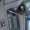
Tip for later model years: To release the lock, you must
open the little access panel and insert a screwdriver into the
hole. Insert only about 1/2" below the sliding metal
piece. The lock release mechanism is a metal lever just below the
hole. It's possible for a small screwdriver to go past the lever
to the side, so it helps to angle the tip of the screwdriver just a
little towards the right (and the handle towards the left). When
you touch the release lever, you should feel a slight springy
resistance. Push it down just a little, then you'll be able to
push the thumb button on the gearshift lever. While still holding
the thumb button, remove the screwdriver, then move the gearshift down
to 1st.
|
|
|
|
|
5. |
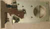
Remove the front ashtray: Open
the ashtray door, and slide the entire ashtray/door assembly straight
out from the dash. |
The SVX has two (2 !) antennas (more about this in section 2.5.5). The antenna
cables coming out the rear of the radio are about 17" long. Even
so, there is only about an inch of slack. Until you unplug these
cables, you won't be able to slide the radio cage out of the dash far
enough to do anything.
The antenna cables have traditional Motorola connectors.
These are located under the carpet on the left side of the transmission
hump, between the back of the radio console and the accelerator pedal
(on Left-Hand Drive cars).
To uncover the antenna connections:
|
1. |
Tilt your steering wheel all the way up (on LHD cars).
|
|
|
|
|
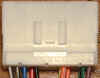
2. |
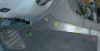 There is a small
plastic trim panel on the left side of the transmission hump, between
the carpet and the radio/gearshift console. It's attached from
behind by three plastic "snap" fasteners. Remove this panel by
lifting it away from the transmission hump. The edge of the panel
nearest to the seat has a tab that interlocks with the next plastic
panel, so you'll need to tilt the piece slightly to separate the two
panels (see large picture for details). Just do this slowly
without using excessive force. There is a small
plastic trim panel on the left side of the transmission hump, between
the carpet and the radio/gearshift console. It's attached from
behind by three plastic "snap" fasteners. Remove this panel by
lifting it away from the transmission hump. The edge of the panel
nearest to the seat has a tab that interlocks with the next plastic
panel, so you'll need to tilt the piece slightly to separate the two
panels (see large picture for details). Just do this slowly
without using excessive force.
|
|
|
|
|
3. |
There is a round, flat-headed plastic "nut" in the carpet,
on the left side of the hump (near the accelerator pedal on LHD
cars). Use a flat-bladed screwdriver to unscrew this nut.
|
|
|
|
|
4. |
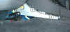 Grab the top edge of the carpet and pull
it away from the hump and down towards the floor. Reach behind
the carpet to grab the antenna cables and disconnect them. Grab the top edge of the carpet and pull
it away from the hump and down towards the floor. Reach behind
the carpet to grab the antenna cables and disconnect them.
|
|
|
|
|
5. |
Make note of how the radio's
antenna cables are routed, so you can run your new antenna cable the
same way. Or if you prefer, attach a 3 foot long piece of string
to one of the radio's cables, to use as a "pull-rope" later. It's
not too difficult to thread the new cable without it, though. |
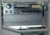
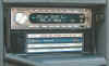
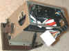
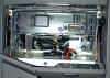
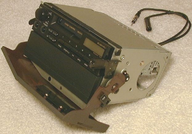
The SVX radio is mounted inside a metal "cage" (AKA "holder" /
"housing" / "can" / "mounting bracket"). The cage does several
things:
-
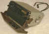 The factory radio (and optional
CD player, or cover plate) bolt to the cage.
The factory radio (and optional
CD player, or cover plate) bolt to the cage.
-
The Audio Cover door and its
hinges, springs, speed dampener, and latch-post are all attached to the
sides of the cage.
-
The cage fastens to the car with
three or four screws. It also rests on a curled, springy metal
support inside the dash opening, at the bottom, towards the rear.
- The black plastic bezel (trim ring that surrounds the faces of
the radio/CD player stack) clips onto the cage.
This is all you need to know for now. Section 2.4.1, below, describes the cage in
more detail (so you can determine what receivers will fit). To
remove the cage assembly:
|
1. |
Open the Audio Cover door.
|
|
|
|
|
2. |
 On the backside of this door, you'll see a black
plastic piece that covers the latch release mechanism. It simply
snaps onto the door. To remove it, raise the door slightly (like
you're starting to close it) and gently pry the black piece apart from
the door. It should be possible to do this without any tools
—
grasp the piece with your fingers wrapped around the back side and
rotate the back up and towards you. If yours is on really tight,
you can carefully pry it off with a small, flat-bladed
screwdriver. After you release the snaps, lift the whole piece up
then out. Click on the picture to see close-up views of the trim
piece. On the backside of this door, you'll see a black
plastic piece that covers the latch release mechanism. It simply
snaps onto the door. To remove it, raise the door slightly (like
you're starting to close it) and gently pry the black piece apart from
the door. It should be possible to do this without any tools
—
grasp the piece with your fingers wrapped around the back side and
rotate the back up and towards you. If yours is on really tight,
you can carefully pry it off with a small, flat-bladed
screwdriver. After you release the snaps, lift the whole piece up
then out. Click on the picture to see close-up views of the trim
piece.
|
|
|
|
|
3. |
 You'll now be
able to see one screw at the bottom of the radio cage. It secures
both the metal cage and the bottom of the black plastic bezel (trim
piece that surrounds the front of the factory radio/CD player
stack). Remove the screw. Be careful not to drop it inside
the dash. This is where a magnetic screwdriver is really
handy. Gavin suggested that some SVX's might have a second screw,
but since neither his, Randy's, nor my car had it, I think this is a
myth. You'll now be
able to see one screw at the bottom of the radio cage. It secures
both the metal cage and the bottom of the black plastic bezel (trim
piece that surrounds the front of the factory radio/CD player
stack). Remove the screw. Be careful not to drop it inside
the dash. This is where a magnetic screwdriver is really
handy. Gavin suggested that some SVX's might have a second screw,
but since neither his, Randy's, nor my car had it, I think this is a
myth.
|
|
|
|
|
4. |
 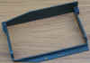 Remove the black plastic
bezel. The top is held in by two prongs that protrude into the
dash cavity (towards the front of the car). It helps to slide the
entire bezel downward (towards the floor); then you can tilt the top of
the bezel away from the radio (towards you). On mine, the left
prong came loose easily. I was able to free the right one by
placing my fingers under the top ledge of the bezel and pushing
upwards, then using that friction to pull the top out. If your
bezel is clipped in really tightly, use a pair of needle-nose pliers to
grab the top ledge and gently pull it out towards you. Once the
top is unclipped, slide the entire bezel outwards (towards you). Remove the black plastic
bezel. The top is held in by two prongs that protrude into the
dash cavity (towards the front of the car). It helps to slide the
entire bezel downward (towards the floor); then you can tilt the top of
the bezel away from the radio (towards you). On mine, the left
prong came loose easily. I was able to free the right one by
placing my fingers under the top ledge of the bezel and pushing
upwards, then using that friction to pull the top out. If your
bezel is clipped in really tightly, use a pair of needle-nose pliers to
grab the top ledge and gently pull it out towards you. Once the
top is unclipped, slide the entire bezel outwards (towards you).
|
|
|
|
|
5. |
 With the bezel
out of the way, you can now see the two screws near the top edge of the
radio cage, on the far left and right sides. Remove these screws. With the bezel
out of the way, you can now see the two screws near the top edge of the
radio cage, on the far left and right sides. Remove these screws. |
|
|
|
|
6. |
Close the Audio Cover door.
The door and latch-post are attached to the radio cage, and will be
coming out along with it. |
|
|
|
|
7. |
Cover the parking brake lever,
the lower part of the center console, and the gearshift lever with a
thick towel. |
|
|
|
|
8. |
 Reach in through
the hole opened up by the missing ashtray and gently slide the radio
cage out toward you. If you can't get enough of a grip on the
bottom of the cage, you can also grab the bottom edge of the Audio
Cover door with your other hand and pull gently. Pull the
cage out about an inch and stop. Reach in through
the hole opened up by the missing ashtray and gently slide the radio
cage out toward you. If you can't get enough of a grip on the
bottom of the cage, you can also grab the bottom edge of the Audio
Cover door with your other hand and pull gently. Pull the
cage out about an inch and stop. |
|
|
|
|
9. |
Now that there's a gap, pull up
the front end of the towel so that it also covers the cigarette lighter
pod. Tuck a little behind the pod so the towel doesn't slide
off. The bottom-left-rear corner of the cage will be squeezing by
here in a moment. |
|
|
|
|
10. |
 Here's where the
plastic putty knife or cardboard rectangles may be necessary: The
hinges of the Audio Cover door stick out the sides of the cage about 1/4"
on the left and 3/8" on the right. These
can snag on the gray trim that folds around the left and right sides of
the center console. There is a small gear on the right side
that's very sharp. Use the putty knife or cardboard like a
shoehorn between the sides of the cage and the console. The
cardboard does a better job of preventing the cage from damaging the
gray trim. Be sure to raise the cardboard up beside the metal
"ears" where the upper screws went. Here's where the
plastic putty knife or cardboard rectangles may be necessary: The
hinges of the Audio Cover door stick out the sides of the cage about 1/4"
on the left and 3/8" on the right. These
can snag on the gray trim that folds around the left and right sides of
the center console. There is a small gear on the right side
that's very sharp. Use the putty knife or cardboard like a
shoehorn between the sides of the cage and the console. The
cardboard does a better job of preventing the cage from damaging the
gray trim. Be sure to raise the cardboard up beside the metal
"ears" where the upper screws went. |
|
|
|
|
11. |
The bottom-front edge of the cage
has a flange, extending down about 1/2".
The bottom screw went through this. It should now be about an
inch forward of the crossbar that the screw attached to. Reach
back into the ashtray hole and continue pulling the cage using the
flange. Don't try to pull or lift the entire weight of the cage
by just the door. |
|
|
|
|
12. |
The very last 1/2"
of the cage has an extra thickness of metal on each side (it's where
the back plate is welded to the sides of the cage). This may
catch on the tabs in the dash where the two upper screws mounted.
Just angle the whole cage right and left slightly and apply a little
more pressure. Watch those sharp edges out front! Pull the
cage all the way out from the console. |
|
|
|
|
13. |
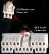 Disconnect the
SVX Radio Connector from the radio (and the two-pin illumination
connector from the CD player, if you have one). There is a lock
button on the top edge of each connector; push it down to unlock. Disconnect the
SVX Radio Connector from the radio (and the two-pin illumination
connector from the CD player, if you have one). There is a lock
button on the top edge of each connector; push it down to unlock. |
|
|
|
|
14. |
Make note of how the factory
radio's antenna cables are routed up here, so you can run your new
antenna cable(s) the same way. Pull the antenna cables completely
out. If you attached a string, re-tie the end on the crossbar for
now. |
|
|
|
|
15. |
Put the cage down somewhere where
it won't scratch anything. |
Before you go any further, check that the SVX's Radio Connector
will plug into the Receiver Wiring Adapter. If they aren't a
matching male/female pair, you'll have to figure out what kind you
really have in the SVX, and get a Receiver Wiring Adapter that does
match (if you can post a picture to the MOD Mania forum at subaru-svx.net, I
might be able to help, but no promises). If the
connectors do look like they match, test the fit. The two
connectors should mate easily; if not, make sure that all the pins
are straight on the Receiver Wiring Adapter.
 The factory radio
and CD player are each attached to the cage by two screws on the left
and right sides. Remove these screws and slide the radio and CD
player out the front of the cage. If the screws have the same
threads as the mounting holes on your new receiver and they are not too
long, reuse them — the heads are a good shape for the
indentations on
the cage. On many receivers, the size and maximum allowed depth
for the screws is stamped on the sides of the metal chassis.
The factory radio
and CD player are each attached to the cage by two screws on the left
and right sides. Remove these screws and slide the radio and CD
player out the front of the cage. If the screws have the same
threads as the mounting holes on your new receiver and they are not too
long, reuse them — the heads are a good shape for the
indentations on
the cage. On many receivers, the size and maximum allowed depth
for the screws is stamped on the sides of the metal chassis.
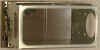
 If your SVX does not have the
factory CD player, then you'll have a cover plate in the lower half of
the cage, held in by two screws. If you'll be installing a
receiver and other components whose total size is larger than a
single-DIN, remove this cover plate.
If your SVX does not have the
factory CD player, then you'll have a cover plate in the lower half of
the cage, held in by two screws. If you'll be installing a
receiver and other components whose total size is larger than a
single-DIN, remove this cover plate.
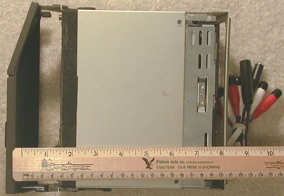
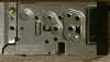
This section should help you figure out whether a particular new
receiver (and any other component) will fit. These measurements
are from my 1996. I've been told that the cage has remained the
same through all of the model years — same part number and
dimensions.
Since you'll probably want to
keep the Audio Cover door, you'll need to reuse the SVX factory cage
with your new receiver. The good news is that you won't need to
buy any kind of "mounting kit." If for some strange reason
you can't or don't want to use the factory cage, you're in for some
major custom metalwork to make a replacement mounting bracket.
Better to reuse the factory cage. At worst, you might need to
drill some new holes in the sides to line up with the mounting holes on
your new receiver.
The interior of the radio cage is 7-1/16"
(17.9cm) wide, 4" (10.1cm) tall, and 6-5/8"
(16.9cm) deep. A single DIN component is 2" tall by 7"
wide. So, the cage can hold one or two single-DIN-sized
components, or one double-DIN-sized component. The depth
measurement does not include the space where a receiver's
faceplate goes; keep reading.
 There is a large opening in the
back of the cage that would allow a new receiver to have protrusions
longer than 6-5/8". But behind the cage you
start running into other structures, ducts, and wiring tubes anywhere
from 0 to 1" further back. And remember, all of that extra
speaker/power wire bundle has to fit back there somewhere.
There is a large opening in the
back of the cage that would allow a new receiver to have protrusions
longer than 6-5/8". But behind the cage you
start running into other structures, ducts, and wiring tubes anywhere
from 0 to 1" further back. And remember, all of that extra
speaker/power wire bundle has to fit back there somewhere.
 There are mounting holes on
each of the left and right sides of the cage, about 7/32"
(6mm) in diameter. The lower DIN bay has two mounting holes per
side. They are both 1" up from the bottom (this is exactly in the
middle of the 2" tall single-DIN slot); one is 1-7/8"
in from the front and the other is 3-1/2" in from
the front. The upper DIN bay has three mounting holes per
side. Two are similar to the lower bay's holes (except they are
1" down from the top — again, exactly in the middle of the 2"
tall
single-DIN slot). The third hole is 5/8"
down from the top and 1-1/16" in from the front.
There are mounting holes on
each of the left and right sides of the cage, about 7/32"
(6mm) in diameter. The lower DIN bay has two mounting holes per
side. They are both 1" up from the bottom (this is exactly in the
middle of the 2" tall single-DIN slot); one is 1-7/8"
in from the front and the other is 3-1/2" in from
the front. The upper DIN bay has three mounting holes per
side. Two are similar to the lower bay's holes (except they are
1" down from the top — again, exactly in the middle of the 2"
tall
single-DIN slot). The third hole is 5/8"
down from the top and 1-1/16" in from the front.
There is a large vent hole on each side. They are
approximately 3-1/8" (80mm) in diameter, about 1/2"
in from the back, and centered 2" up/down from the bottom/top.
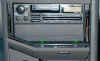
From the front edge of the cage to the rear of the Audio Cover
door (when closed) there is anywhere from 7/8"
to 2" space. The smallest clearance is in the upper bay, on the
side above the cigarette lighter. The largest is in the
lower bay. This is how much room you'll have for your new
receiver's faceplate and any protruding knobs or buttons. The
front of my JVC's chassis mounted flush with the front edge of the cage.
You can gain a little more space by not re-installing the black
plastic piece that came off the backside of the Audio Cover door (the
part you removed in step 2 of section 2.3.3,
above). I read that a stereo installer melted a smooth, round
hole in that piece to leave clearance for a tall volume knob on a
customer's receiver.
Bear in mind that since the front of the cage is inset into the
dash (below the Climate Control pod), a receiver with an oversized
foldout face that extends above the top of the receiver won't fit in
the upper DIN bay. Similarly, one whose face folds down below the
bottom of the receiver won't fit in the lower DIN bay.
Here's a link to an exploded diagram of the radio cage in the 1992
SVX, from SubaruParts.com.
You can edit the "1992" in the URL to see the other model years, but
all are very similar. The diagram also lists the prices for the
individual parts and assemblies — make sure you're sitting down
when
you read these. Prices from Subaru dealerships are even higher!
|
1. |
If your new receiver has a
removable faceplate, leave it off to keep from scratching it, except
while you check for fit.
|
|
|
|
|
2. |
If there is a support bolt or stud protruding from the rear
of your receiver (possibly with a rubber cap on the end), remove
it. It is not needed on the SVX, and would just prevent you from
sliding the cage all the way back into the dash.
|
|
|
|
|
3. |
Most DIN-sized receivers include a metal mounting sleeve
that slips around the front. You won't need this to install the
receiver in the cage.
|
|
|
|
|
4. |
Slide your receiver into the cage.
|
|
|
|
|
5. |
Determine the proper depth that
you need to mount your receiver in the cage for the faceplate to work
(i.e., so you can flip it open to load a CD, or to remove it, if it
does either). Verify that the Audio Cover door can still open and
close completely. If it looks like it will be a tight fit,
temporarily reinstall the black plastic cover piece that goes on the
back side of the Audio Cover door (the part you removed in step 2 of section 2.3.3, above). If
your receiver has a motorized door, you might even need to wire up the
harness and plug it in temporarily so you can make sure the receiver's
door will have room to work. |
|
|
|
|
6. |
If the existing mounting holes on
the sides of the cage line up with mounting holes on your receiver,
great! Use either the screws from the factory radio (if they're
the correct thread and not too long), or else screws that came with
your new receiver. The existing holes worked for Gavin's Sony,
Randy's Blaupunkt, and my JVC.
If the holes in the cage do not line up with ones on your
receiver, you'll have to drill some new ones. Measure very
carefully. Consider using a drill press to make these
holes. At the very least, clamp the cage to your workbench in a
way that keeps the door and its hardware from being damaged while you
drill.
If you need to make any more extensive modifications to the
cage, you're on your own. If you're not sure what to do, try
posting a message on the MOD Mania forum at subaru-svx.net.
|
|
|
|
|
7. |
If you're adding a CD changer,
amplifier, satellite radio receiver, or any other component to the
second DIN bay, repeat these steps. |
|
|
|
|
8. |
Check the fit of the SVX's bezel
(the part you removed in step 4 of section
2.3.3, above). You may need to trim or file it to fit around
your new receiver. Mine fit with no modification needed. I
also did not need to use my receiver's faceplate trim ring. |
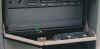
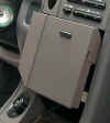
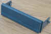
 Most after-market receivers
today are single-DIN sized. If you aren't planning to install a
second component in the other DIN bay, a plastic pocket makes much
better use of the space than a simple cover plate. It gives you a
convenient place to store things like CDs and sunglasses. I
wouldn't put candy bars in there though; the pocket can get fairly hot
from the transmission and receiver.
Most after-market receivers
today are single-DIN sized. If you aren't planning to install a
second component in the other DIN bay, a plastic pocket makes much
better use of the space than a simple cover plate. It gives you a
convenient place to store things like CDs and sunglasses. I
wouldn't put candy bars in there though; the pocket can get fairly hot
from the transmission and receiver.
In addition to selling new pockets, many stereo install shops have
a pile of ones they've removed from other vehicles. If you ask
nicely enough, they'll probably give you one free. Crutchfield
also carries new ones, and might give you one free when you order a car
receiver from them.
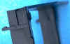
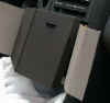
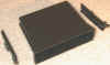 The nice folks at Crutchfield
gave me a model UPK-750 pocket by American International that works
very well. It's actually intended for a whole bunch of other
cars, including 1994-2000 Ford Mustangs. It has room to hold four
single-CD jewel cases. What's really nice about this pocket is
that it has side rails that mount to the cage. The pocket itself
just slides onto the rails. So you can leave it out while you
reinstall the cage, and slide in the pocket as a final step. With
the pocket gone, you can reach in and guide the wires out of the way as
you slide the cage back into the dash.
The nice folks at Crutchfield
gave me a model UPK-750 pocket by American International that works
very well. It's actually intended for a whole bunch of other
cars, including 1994-2000 Ford Mustangs. It has room to hold four
single-CD jewel cases. What's really nice about this pocket is
that it has side rails that mount to the cage. The pocket itself
just slides onto the rails. So you can leave it out while you
reinstall the cage, and slide in the pocket as a final step. With
the pocket gone, you can reach in and guide the wires out of the way as
you slide the cage back into the dash.
For the UPK-750 to fit, you'll need to cut off the tip of one post
on each of the side rails. Then mount the rails to the cage with
one screw per side, using existing mounting holes in the cage.
Don't tighten the screws completely, or the pocket won't engage the
rails. Some shims might help. Practice sliding the pocket
in and out while the cage is out of the car.
Although the kit includes a trim ring for the front, it reduces
the size of the opening to where only three CDs would fit. Plus,
it's about 1/16" too wide — that excess
would
have to be filed off for it to fit inside the cage. So I decided
not to use the pocket's trim ring.
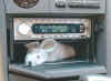
Some people have installed extra gauges in the lower DIN space
(e.g., transmission oil temp, oil pressure, voltmeter, air/fuel ratio,
etc.). Although the specifics go beyond the scope of this
document, I mention it here as food for thought. Someone also
mentioned hamsters.
Gavin created the original version of the following table based on
information from a 1994 Service Bulletin. I've added the
information in Column "B" and for pins 4, 13, 14, 15, and 16:
Table 2.5.1
Subaru SVX Radio Connector
(Speaker / Power Wiring)
Pin Assignments |
|
Pin #
|
Function
|
Column "A"
SVX Radio Connector
Wire Color
to car's Speakers, etc.
|
Column "B"
Receiver Wiring Adapter
Wire Color
(EIA Standard)
to Receiver
|
1 |
Right Rear
Speaker + |
Blue / Yellow |
Violet |
2 |
Left Rear
Speaker + |
White / Red |
Green |
3 |
(none) |
NC |
NC |
4 |
Illumination
+ * |
Red |
Orange* |
5 |
+12 Volt
Memory |
Blue / Red |
Yellow |
| |
(gap for
connector lock) |
|
|
6 |
+12 Volt
Accessory |
Brown / Red |
Red |
7 |
(none) |
NC |
NC |
8 |
Right Front
Speaker + |
Red / Yellow |
Gray |
9 |
Left Front
Speaker + |
Brown / White |
White |
| |
|
|
|
10 |
Right Rear
Speaker - |
Red / White |
Violet / Black |
11 |
Left Rear
Speaker - |
Red / Black |
Green / Black |
12 |
(none) |
NC |
NC |
13 |
Dimmer
(Illum. -)* |
Red / Black |
Orange / White* |
14 |
Night Illum.
Dimness Cancel.* |
Pink |
[Orange /
Black]* |
15 |
Phone Mute |
NC |
NC |
16 |
Audio
Satellite Switches |
Black / White |
NC |
17 |
Ground |
Black |
Black |
18 |
Power Antenna
+ |
Black / Green |
Blue |
19 |
Right Front
Speaker - |
White / Black |
Gray / Black |
20 |
Left Front
Speaker - |
Green |
White / Black |
*
Illumination and Dimmer Wires — see table 2.5.2a, below
Notes:
|
a. |
 The pin numbers
are stamped on the sides of the connectors, on the hinged flaps at the
rear that lock in the wires. The numbers are very hard to read
until you hold the connector at just the right angle in the light. The pin numbers
are stamped on the sides of the connectors, on the hinged flaps at the
rear that lock in the wires. The numbers are very hard to read
until you hold the connector at just the right angle in the light.
|
|
|
|
|
b. |
When two colors are listed, the first is the main color and
the second is the stripe color.
|
|
|
|
|
c. |
"NC" means there is no metal contact at that position in the
connector shell (and thus no wire).
|
|
|
|
|
d. |
Column "A" lists the wires on the SVX Radio Connector.
This is the plug whose wires disappear behind the dash and go to the
speakers, etc. Randy confirmed that the wiring is the same as his
1992, Gavin his 1995, and I my 1996. You might want to verify
that the wires on the connector in your car match this column,
just to be sure a previous owner or car stereo installer didn't change
your car's wiring.
|
|
|
|
|
e. |
Beware that the SVX Radio
Connector has two Red / Black wires (pins 11 and 13). Both stripes are
exactly the same (i.e., one isn't "spiraled"). Aren't you glad
you don't need to cut off this connector or splice into these wires
anymore? |
|
|
|
|
f. |
Column "B" lists the wires on the
Receiver Wiring Adapter
(the part that you will crimp or solder to your receiver's
wires). These are the EIA standard wire colors, used by
after-market receiver and wiring adapter manufacturers. Use this
column to verify that the adapter was assembled correctly (and, if you
remove the wires from the shell while you solder them, use this column
when you re-insert them). |
|
|
|
|
g. |
The wires on your new
after-market receiver will likely be colored the same as Column
"B" but may not be. Please check your receiver's
installation instructions to be certain! Connect the wires
according to function, not necessarily by color. If the
manuals are missing, look on your receiver manufacturer's web site for
online or downloadable copies (perhaps under "Technical Support"). |
|
|
|
|
h. |
There are three pins related to
dash illumination — 4, 13, and 14. They are described in
detail
in section 2.5.2, below. |
|
|
|
|
i. |
There are no separate terminals
on the SVX Radio Connector for the tweeters. These speakers
connect in parallel to the door speakers, branching off at points
behind the dash. Even if your SVX did not come with factory
tweeters, it still has the wires and connectors, ready for you to add
your own (covered in section 3). |
Here is the SVX Radio & Clock Wiring Diagram (JPEG file,
214,844 bytes), scanned from a Subaru service manual (year
unknown). Notes about this diagram:
|
j. |
"L" stands for Blue; "Br" for Brown; "B" for Black.
|
|
|
|
|
k. |
The Illumination (pin 4) and Dimmer (pin 13) wires disappear
into the dash along with all of the other wires. They do not just
loop back into the CD Illumination connector (as indicated by the
diagram). These pins, plus Dimmer pin 14, all receive power from
the dash illumination/dimmer circuitry (from the Time Control
Unit). See section 2.5.2
for more about the Illumination wires, and section
2.5.3 for more information on the TCU.
|
|
|
|
|
l. |
 Pin 16 really
does have a contact and wire (Black with White stripe). This is
for the "audio satellite switches" (buttons for radio power on/off,
volume up/down, AM/FM, etc.) on the steering wheel in some JDMs
(Japanese Domestic Models). And before anyone asks, no, it does
not have buttons labeled "A" for jacks, "B" for enhanced tire treads,
"C" for buzz saws, ... Pin 16 really
does have a contact and wire (Black with White stripe). This is
for the "audio satellite switches" (buttons for radio power on/off,
volume up/down, AM/FM, etc.) on the steering wheel in some JDMs
(Japanese Domestic Models). And before anyone asks, no, it does
not have buttons labeled "A" for jacks, "B" for enhanced tire treads,
"C" for buzz saws, ...
|
|
|
|
|
m. |
There is no crossover circuitry
(low-pass/high-pass filter) in the SVX's speaker wiring. If you
need this (e.g., for new tweeters), you'll have to add your own.
Many (most?) new component tweeters include their own crossovers. |
Many receivers today have an Illumination or Dimmer wire.
This section will help you decide where to connect it.
There are three (3 !) wires on the SVX Radio Connector related to
instrument illumination. If you want to know why, take a close
look at your dash one night (especially the radio) and watch how many
different ways all of the lights change brightness as you play with the
various light controls (see below). Here's what these wires do in
my 1996 ("your mileage may vary"):
Table 2.5.2a
SVX Radio Connector
Illumination and Dimmer Pins |
| Pin # |
Measured voltages (with respect to ground) |
| |
Default |
When
{Ignition switch is On} AND
{Headlights switch is on Parking OR Headlights} |
| 4 |
Normally 0 volts. |
Becomes +12 volts. Unaffected by
the instrument Illumination Brightness Control, or by the BRIGHT switch. |
| 13 |
Normally 0 volts. |
Varies from +10 down to 0 volts as the
instrument Illumination Brightness Control is rotated from dimmest to
brightest, respectively (i.e. "dimmest" = +10 volts, "brightest" = 0
volts). Unaffected by the BRIGHT switch. |
| 14 |
Normally about +0.75 volts (even when
Ignition is Off). |
Becomes +12 volts. When BRIGHT switch
pressed (dash in "bright" mode), goes back to +0.75 volts. Press
BRIGHT again (dash in "normal" mode), returns to +12 volts.
Unaffected by the Illumination Brightness Control. |
None of these wires are affected by the Parking light switch
—
this switch only activates the exterior parking/marker lights, not the
instrument illumination.
Just so everyone knows what I'm talking about, these are the
"official" names for the various switches (from the 1996 SVX owners
manual):
|
Table
2.5.2b
SVX Headlights / Dash Illumination Controls
|
| "Official"
Name |
Description |
|
Headlights switch
|
Three position "knob" (Off / Parking / Headlights) near the
tip of the turn signal lever.
|
|
Instrument Illumination Brightness Control
|
Dimmer ring, on the turn signal lever just to the right of
the Headlights switch.
|
|
BRIGHT switch ("Night Illumination Dimness Cancellation")
|
Button (momentary, but works like a push on / push off) on
the tip of the turn signal lever.
|
|
Parking light switch
|
Button (push on / push off) next to the Remote Control
Mirror Switch.
|
Most aftermarket receivers have a dimmer wire (a few don't).
Of those that do, nearly all of them intend for you to connect that
wire to one in your car that has +12V when your headlights are on, and
0V when your lights are off. On the SVX, that is pin 4 (Orange
wire on my harness). This will cause the receiver to be at full
brightness when your lights are off ("day" mode), and slightly dimmed
when your lights are on ("night" mode).
Note that on receivers that have a dimmer wire, most also have a
related menu option for "dimming." Be sure to enable that option (set
it to detect the voltage on the dimmer wire). Also, some
receivers
may only dim the backlighting for the alphanumeric display (and not
the backlighting for the buttons and knobs).
No receiver that I'm aware of today is able to vary the brightness
gradually (the way your instrument panel illumination does). Even for
the rare ones that do, they expect to see the voltage go from 0
(dimmest) to 12 (brightest) — opposite from the way Subarus work.
So pin 13 won't do what you might have wanted.
In theory, pin 14 should make the illumination work more like on
the factory radio —
bright when lights are off, dim when you first turn on your headlights,
and back to bright when you press the car's BRIGHT button. At the time
I first wrote this guide, however, all of the receivers I
tested stayed in "night" mode all the time, due to the slight voltage
present on pin 14 even when the headlights were off.
Since pin 14 didn't work for me, I also tested pin 13. I
found that I preferred the way it worked over pin 4: When the
headlights
were off, the receiver's display was in "bright" mode. With
the headlights on and the Instrument Illumination Brightness Control
set
anywhere from dimmest up to the last-detent-before-brightest (where I
normally keep it), the display was dimmed. Rotating
the IIBC to the brightest position caused the receiver's display to go
back to "daylight" brightness, which I would use whenever I turned on
my headlights during daylight.
More recently, several people have told me that pin 14 worked well
with their receivers. Newer receivers require a higher voltage to
change to "night" mode (6 Volts for some). The ones I had tested
switched at around 0.7V. For those, you can use a small silicon
diode in series to reduce the car's voltage by 0.7V. The result
should be just low enough for the receiver to stay in day mode until
you
actually turn on the headlights (and again when you press the BRIGHT
button).
So my recommendations now are:
-
Connect temporarily to pin 14 and test. If it works
(bright with headlights off, dim
with headlights on, back to bright when you press the BRIGHT button),
then make your connection permanent.
-
If that doesn't work, insert a silicon diode (e.g., 1N4001) in
series.
Connect
the cathode (the terminal marked with a stripe) to your
receiver's dimmer wire and the anode to pin 14. Test again.
-
If that doesn't work (or you don't want to bother with a
diode), try pin 13. With this wire, your receiver's display
should be bright with headlights off, and dim when headlights are on
(but only when you set the IIBC below a certain point). That
point
will vary with different receiver models.
-
If you don't like how that works (or you don't want your
dimmer
knob to affect your receiver's brightness), use pin 4.
The SVX has six fuses for circuits that are connected to the
radio
(four directly, and two indirectly). If random things stop
working in your SVX, this information may help you track down whether
your radio installation was at fault:
-
15 Amp fuse No. 17 (on the
interior fuse panel, below the hood release) provides main power to the
radio connector (pin 6). This circuit is powered when {Ignition
switch is ACC or ON}. If your new receiver draws more than 15
Amps through the +12V Ignition/Switched (Accessory) wire, you'll need
to either replace this fuse, or run a new power wire.
-
10 Amp fuse No. 25 (on the fuse
panel under the hood, between the battery and the engine coolant
reserve tank) supplies "memory" power to the radio connector (pin
5). This circuit is always on. It also powers the timer
portion of the SVX's clock and part of the Time Control Unit (TCU, pin
"b2"). If your new receiver draws more than 10 Amps through
the +12V Battery/Constant (Memory) wire, you'll need to either replace
this fuse, or run a new power wire.
-
15 Amp fuse No. 22 (under the
hood) powers the telescoping power antenna. This circuit is hot
even when the ignition is off. Pin 18 on the Radio connector just
provides a low-current (+12V at about 50mA) control signal to the
antenna motor.
-
10 Amp fuse No. 9 (interior fuse
panel) goes to Illumination pin 4 on the radio connector. This
circuit is on when {Ignition is ACC, ON, or START} and {Headlights
switch is on Parking or Headlights}. It also goes to one side of
all of the instrument illumination (green) bulbs, and into pin "a3" on
the TCU (so this is the +12V side of the instrument illumination
bulbs).
-
20 Amp fuse No. 3 (interior fuse
panel) goes to TCU pin "a7." This circuit is on when {Ignition is
ACC or ON}. Also lights up the clock display.
-
10 Amp fuse No. 15 (interior
fuse
panel) goes to TCU pin "b9." This circuit is on when {Ignition is
ON or START}. Also powers "Meter."
In addition to handling nearly all
of
the things that need timing (e.g., wiper delay, rear defogger cutoff,
seat belt buzzer, automatic shoulder belt system, courtesy
illumination, etc.), the TCU also manages the instrument illumination
and dimming.
TCU pin "a20" goes to Dimmer pin 13
on
the radio connector, and to the other side of all of the instrument
illumination (green) bulbs. This is the side of the bulbs that
varies from +10 down to 0 volts as the lights go from dimmest to
brightest. It's a good bet that Fuse No. 9 powers this circuit.
TCU pin "a2" feeds Dimmer pin 14 on
the radio connector. I'm guessing that Fuse No. 9 powers this
circuit as well.
This is the point where Gavin and Randy wrote about cutting the
wires on the SVX's Radio Connector. Other people have used
T-splices to tap in to the SVX's wires. But those days are
over! Now you'll simply be joining your new Receiver's Wiring
Harness to the Receiver
Wiring Adapter. Warm up your soldering iron or grab your
crimp tool.
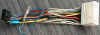
|
1. |
It's going to be very cramped behind the cage. So
first determine how long you want the wires. Shorter means less
to stow behind the cage. But too short may not let you put the
big connectors where they will fit. With the receiver in the
cage, temporarily plug in the Receiver Wiring Harness to see how you
will route the wire bundle. Before you shorten the wires, be sure
you will be leaving enough length to slide the heat shrink tubing out
of the way while you solder.
|
|
|
|
|
2. |
Use your receiver's instructions to determine which wires
you won't be using. You might want to shorten them even
more (exception: wires that you could decide to use later, such as for
an amplifier). If they are pre-stripped, at least cut off the
bare ends.
|
|
|
|
|
3. |
 Similarly, use
table 2.5.1 to decide which of the pins on the Receiver Wiring Adapter
you won't be using. You can either shorten them as above, or
remove the entire wire and contact pin from the connector shell. Similarly, use
table 2.5.1 to decide which of the pins on the Receiver Wiring Adapter
you won't be using. You can either shorten them as above, or
remove the entire wire and contact pin from the connector shell.
|
|
|
|
|
4. |
Strip about 1/2" of insulation from
each of the wires you will be using. If they're pre-stripped, but
longer, cut the bare ends down to this length.
|
|
|
|
|
5. |
If you're soldering, slide a 2"
piece of heat-shrink tubing down each of the wires on one of two
connectors. Even if you're crimping, you might still want to
cover the crimps with heat-shrink. I don't recommend electrical
tape — in my experience, the adhesive comes loose in the heat,
and
these connections are going in a place that will get very warm. |
|
|
|
|
6. |
Connect the wires according to function,
not necessarily by color. For example, look in your receiver's
instructions to see which wire is for the Power Antenna control and
even if it's, say, Pink on the Receiver's Wiring Harness, connect that
wire to the Receiver Wiring Adapter's Blue "Power Antenna" wire (pin
18). Watch out for the wires with black stripes — don't
confuse
them for the ones without. It's a good idea to do this work
somewhere that's well lit. |
|
|
|
|
7. |
 If you're
soldering, join the wires in-line. See the example. This
gives the best shape to cover with the heat-shrink tubing, and will
make the bundle easier to manage. If you're
soldering, join the wires in-line. See the example. This
gives the best shape to cover with the heat-shrink tubing, and will
make the bundle easier to manage. |
|
|
|
|
8. |
Double-check your connections. |
|
|
|
|
9. |
Slide a piece of heat-shrink
tubing down each of the unused wires from steps 2 and 3 above. |
|
|
|
|
10. |
 Center each piece
of heat-shrink tubing over the joint (this is where clear-colored
tubing helps) and apply heat. If you're using a butane lighter
and haven't done this before, practice a few times on scraps of wire
—
it's very easy to burn the heat-shrink tubing. Center each piece
of heat-shrink tubing over the joint (this is where clear-colored
tubing helps) and apply heat. If you're using a butane lighter
and haven't done this before, practice a few times on scraps of wire
—
it's very easy to burn the heat-shrink tubing. |
|
|
|
|
11. |
  A nice touch is to add spiral wrap around the whole
wire bundle. This gives an extra layer of protection against the
bundle being pinched between the cage and something else. I also
put some around the SVX's speaker/power wire bundle, all the way back
to where it disappears inside the dash. A nice touch is to add spiral wrap around the whole
wire bundle. This gives an extra layer of protection against the
bundle being pinched between the cage and something else. I also
put some around the SVX's speaker/power wire bundle, all the way back
to where it disappears inside the dash. |
As mentioned back in section
2.3.2, the SVX and factory radio have two antenna cables. One
cable goes to the telescoping power antenna. The second cable
connects to the rear window defogger (which doubles as an antenna).
The factory radio uses a feature called "Diversity" for better
FM
reception — it picks whichever antenna is getting the stronger
reception at any moment. How can the rear window defogger make
that much difference? You might have experienced this in a car
with a single antenna: While slowly rolling up to a traffic light, the
reception on a particular FM station drops suddenly or gets lots of
static. Just moving the car forward by a foot or two makes the
signal return. With Diversity, in many such situations the two
antennas are far enough apart for one of them to "see around the
obstruction."
Unfortunately, receiver manufacturers have stopped including
Diversity. According to the folks at Crutchfield, the last model
they sold that had it was in 2001. What this means to you?
Unless you've bought an older receiver that has Diversity (i.e., has
two antenna cables), you'll only need to connect one antenna to your
receiver. Don't use a Y-adapter to connect both antennas
to a non-Diversity receiver. That will give you worse reception
than just using the SVX's power antenna alone (it's an
"impedance-mismatch" thing).
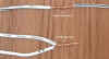
Make your antenna connections:
|
1. |
Take the SVX antenna cable that ends with the male
Motorola
plug (fatter diameter cable, with the pointy end). This is the
cable that comes from the telescoping power antenna. Connect this
cable to the female end of your antenna extension cable. If your
replacement receiver has Diversity, take the other SVX antenna cable
(terminated with a female Motorola jack, with the thinner diameter
cable), connect a second extension cable, and run both extensions at
the same time.
|
|
|
|
|
2. |
Thread the other end of the extension cable(s) through the
back of the center dash console, up to the large opening where the
factory radio was. Leave the end(s) dangling for now —
don't
connect to your receiver yet.
|
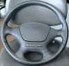
Gavin's Sony came with a wired remote control. Here's his
description of the installation:
I mounted it on the right-hand side of the steering column
below
and slightly behind the windshield-wiper controls. This puts it
in easy reach but stops it getting in the way of other controls.
This was a pretty simple matter of removing the top of the steering
column by releasing the screws on the underside and popping it off (it
does clip as well so don't be afraid to use a little force). Then
I pulled down the section of the underside of the dash where the
coin-holder is (totally useless BTW) [the 1996 and 1997 models have an
engine diagnostic connector there instead -DC]... that section just
clips into place BTW. Anyway, I opened that up and there's a hole
right there leading into the stereo bay. Obviously I did this
before putting the stereo back in place. By the way, there's a
nice gap in the steering column where you can run wires through... very
handy for this kind of thing.
Randy mounted his receiver's remote control in one of the holes
between the "spokes" of his steering wheel. He didn't mention it,
but if it was the wired type, I'm sure he ran the wire the same as
Gavin did.
While a few receiver models still have wired remotes, the
infrared
wireless type is common now. Most are handheld, but some wireless
ones are still shaped to be attached to the steering wheel.
Now is the time to check that everything works, before
you
slide the cage back in. Trust me: you don't want to do that
any more times than absolutely necessary.
|
1. |
Move the gearshift lever back to Park (so you can remove
your key when you turn the ignition back off).
|
|
|
|
|
2. |
Make sure your towel is back in place to protect the
parking
brake lever, console, and gearshift lever.
|
|
|
|
|
3. |
Connect the Receiver's Wiring Harness to the receiver.
|
|
|
|
|
4. |
Plug the SVX Radio Connector into the Receiver Wiring
Adapter. Again, the two connectors should mate easily; if
not, look at the Receiver Wiring Adapter and check that all its pins
are straight. You should feel and hear the lock "click" when the
two connectors mate completely.
|
|
|
|
|
5. |
With the towel still covering
everything, rest the cage on the center console — the combined
wiring
should be long enough (if not, carefully prop the cage on top of the
gearshift lever). |
|
|
|
|
6. |
If it will reach, connect the
antenna cable. If it won't reach, try connecting a short piece of
wire to the receiver's antenna jack to temporarily get radio
reception. Use a large-gauge wire and strip 1/2
to 1" of insulation from the end. |
|
|
|
|
7. |
Reconnect the wire to the
negative terminal of the car battery. |
|
|
|
|
8. |
Turn the ignition to ACC. |
|
|
|
|
9. |
Turn on the receiver. |
|
|
|
|
10. |
At this point, Gavin wrote:
If you find that you've got
power to, say, eject a CD, but there seems to be no power to the unit
to actually play then chances are you've blown a fuse.
Many (most?) receivers today have their own mini-blade
type
fuse in a socket on the rear of the receiver. Check this first
(since it's easiest to access), then the SVX's fuses. See section 2.5.3, above, for the other fuses.
|
|
|
|
|
11. |
Use your balance and fader
controls to be sure you've connected the speakers correctly —
left/right, front/rear. |
|
|
|
|
12. |
Spend a few minutes testing all
of your new receiver's features (to make sure you didn't get a
defective unit). |
Does everything work? If so,
you're almost done...
Because of the excess wire and the
cramped space, this may take more than one try. If the cage gets
stuck, don't force it. Use a flashlight to try to see what's
catching.
Update:
New tip — tie one or more short pieces of string to the
harness. Thread the opposite end of each string into the opening
where the factory radio harness wires go back into the dash.
Continue "fishing" the string out to the right side footwell, so you
can grab the end. When you slide the cage into the dash, use the
string(s) to pull all of the wiring into the opening (rather than
trying to make the wires fold in the limited space behind the cage).
|
1. |
If you went with the slide-in style of pocket, remove it
now. You may need to open the Audio Cover door a bit wider for
the pocket to pass by. The cardboard "shoehorn" helps here.
|
|
|
|
|
2. |
Move the gearshift lever to 1st gear again (same as before
— section 2.3.1).
|
|
|
|
|
3. |
 Make sure none of the SVX's
wires inside the dash will be in the way. Randy noted: Make sure none of the SVX's
wires inside the dash will be in the way. Randy noted:
On the '92 there is a bundle of wires [on the left side
-DC] that appear to come from the [Climate Control] pod that may get in
the way. Pull these toward the front of the cavity that the stereo
resides in.
On my '96, those wires were already strapped out of the way,
and weren't a problem.
|
|
|
|
|
4. |
Make sure your towel is covering the top of the cigarette
lighter pod again.
|
|
|
|
|
5. |
Close the Audio Cover door. |
|
1. |
Hold the cage near the dash
opening. |
|
|
|
|
2. |
 Try to "pre-bend"
the speaker/power wire bundles so that they will fold up behind the
cage when you push it back in. Try to "pre-bend"
the speaker/power wire bundles so that they will fold up behind the
cage when you push it back in. |
|
|
|
|
3. |
If you didn't install anything in
the second DIN bay, route the bundles into that empty space.
If both DIN bays are full, you might be able to tuck some of the SVX's
bundle into the gaps in the very rear of the dash opening, on the
bottom and/or to the right. Ideally, you want the union of the
Receiver Wiring Adapter connector and SVX Radio Connector to end up
flat against the back "wall," at the bottom, with the wires going
left/right. |
|
|
|
|
4. |
If you didn't connect the antenna
cable(s) yet, do that now. Pull as much of the slack as possible
back to the side of the transmission hump. |
|
1. |
Begin sliding the cage back in. If it seems to not
want to even start, refer to section
2.3.3, step12.
|
|
|
|
|
2. |
Now is a good time to insert the two rectangles of cardboard
("shoehorns") on the sides of the opening. Or use the plastic
putty knife on the right side — cover the sharp gear on that side
of
the cage.
|
|
|
|
|
3. |
While you can still see them, watch where the wires are
going. If you use a slide-in style of pocket, reach in through
that hole to guide the wires. Prevent wires from being pinched
between the cage and the dash structures, particularly the cross bars
on the bottom and the vertical struts at the rear.
|
|
|
|
|
4. |
If your Climate Control wires bulge out like in Randy's '92,
use his advice:
Cock the front of the [cage] slightly toward the left as
if to push the unit in toward the right-hand side of the car.
This should help to get past the bundle of wires.
|
|
|
|
|
5. |
Continue sliding the cage
in. When the back of the cage hits the curled, springy metal
support in the dash, you may need to angle the rear of the cage up
slightly to get over that hump. Pause when there's about an inch
left to go. |
|
|
|
|
6. |
Remove the towel from the top of
the cigarette lighter pod. |
|
|
|
|
7. |
 Slide the cage in the last
inch. The flange on the bottom-front edge of the cage should be
flush with the dash crossbar behind it. Slide the cage in the last
inch. The flange on the bottom-front edge of the cage should be
flush with the dash crossbar behind it. |
|
|
|
|
8. |
Reinstall the upper screws.
The magnetic screwdriver is even more helpful here. Otherwise,
use needle-nose pliers to hold each screw. Raise the cage upwards
slightly (towards the Climate Control pod) when you tighten the screws. |
|
|
|
|
9. |
Reinstall the ashtray. |
|
|
|
|
10. |
Check that the Audio Door opens
and closes properly. If not, grab the cage (preferably, using the
pocket), loosen the two screws, and reposition the cage until the Audio
Door doesn't bind. I found that if the cage was too high, the
door would hit the top before it could latch, and if the cage was too
low, the door would scrape against the cigarette lighter pod. |
|
|
|
|
11. |
Replace the SVX's bezel. |
|
|
|
|
12. |
Reinstall the lower screw(s). |
|
|
|
|
13. |
Reinstall the black plastic piece
on the back of the Audio Cover door. If you need extra clearance
for tall knobs on the face of your new receiver, leave this piece off. |
|
|
|
|
14. |
Clean up the antenna cables on
the side of the hump, push the carpet back into place, replace the
plastic nut, and snap the trim panel back on. |
|
|
|
|
15. |
If you have the wireless entry /
security system and you disconnected the car battery, go through the
procedure to "relearn" your remote transmitters. |
 Enjoy your new receiver.
Hmm... Now I think I need some new speakers...
Enjoy your new receiver.
Hmm... Now I think I need some new speakers...
[Table
of Contents] [Section 1:
Introduction] [Section 2: Radio Removal / Replacement] [Section
3: Speaker Removal / Replacement] [Section
4:
Final Notes] [Next] [Previous]
©
Copyright 2002-2010
by David Carter. All rights reserved.


 The factory radio
and CD player are each attached to the cage by two screws on the left
and right sides. Remove these screws and slide the radio and CD
player out the front of the cage. If the screws have the same
threads as the mounting holes on your new receiver and they are not too
long, reuse them — the heads are a good shape for the
indentations on
the cage. On many receivers, the size and maximum allowed depth
for the screws is stamped on the sides of the metal chassis.
The factory radio
and CD player are each attached to the cage by two screws on the left
and right sides. Remove these screws and slide the radio and CD
player out the front of the cage. If the screws have the same
threads as the mounting holes on your new receiver and they are not too
long, reuse them — the heads are a good shape for the
indentations on
the cage. On many receivers, the size and maximum allowed depth
for the screws is stamped on the sides of the metal chassis. If your SVX does not have the
factory CD player, then you'll have a cover plate in the lower half of
the cage, held in by two screws. If you'll be installing a
receiver and other components whose total size is larger than a
single-DIN, remove this cover plate.
If your SVX does not have the
factory CD player, then you'll have a cover plate in the lower half of
the cage, held in by two screws. If you'll be installing a
receiver and other components whose total size is larger than a
single-DIN, remove this cover plate.